This is the Hardware Schematic used for the project.
Schematic Editor
Red Lines
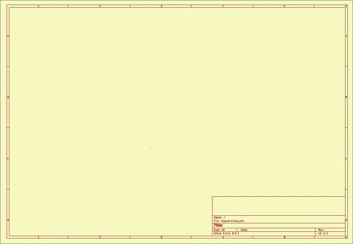 These are the segments of the editor where the schematic lies. It can be configured to be larger
Op-Amp Symbol
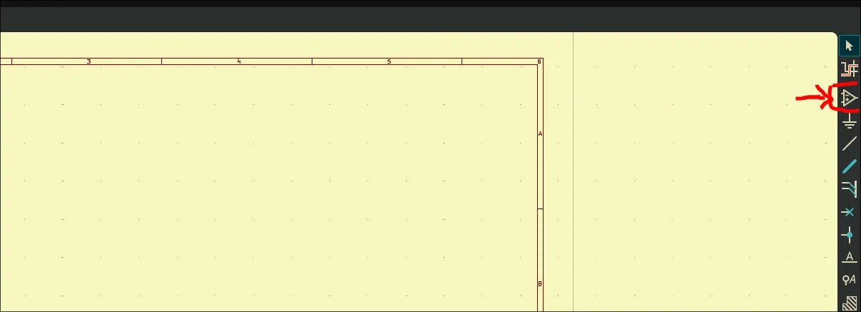 This loads all custom defined symbols loaded from KiCad Symbols.
Ground Symbol
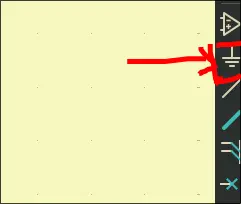 This opens up the symbol menu for all power symbols including:
Thin Wire
This allows creation of wires
Thick Wire
This allows creation of Data Bus
Blue Cross
Used to mark that a pin should be left unconnected and unused.
Wire with ‘A’
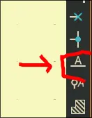 Used to label wires
Global Labels
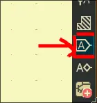 These will label any component
R?? - R42
This option annotates components in case some compnents have no number
Assign Footprints
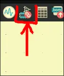 This will assign real life footprints for your schematic through a menu
Electric Rules Checklist
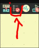 Will prescribe any electrical issues with the schematic