My Gateron Low Profile Keyboard Build Log
Yoshixi
These past few months, I have spent 200 dollars breaking expensive equipment and inhaling toxic fumes all to make an ergonomic split keyboard with as little cost as possible.
Turns out, there were a lot of things I did wrong, and to be honest I should have followed a full guide. But, perhaps my mistakes can be of use to anybody else looking to start this hobby.
Il go through my entire process of setting up my keyboard, along with all the mistakes I made along the way.
1. Determine The PCB
I went into this without a clear guide of what I wanted to make. I had this one thought - that it had to be cheap.
Unfortunately, This lead me to first picking the ferris sweep - shown below:
For background, this is a reversible PCB (This means that the left-side and right-side of the keyboard can use the same PCB) that supports Kailh Choc V1 Switches, something that has a completely different build form than MX Switches
Without knowing this, I proceeded to buy Gateron Milky Yellows, which are of the MX build form. This mean I couldn't build anything lol.
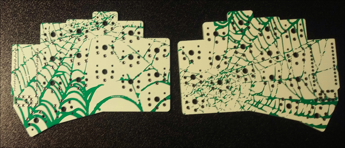
I attempted to rectify this by printing another PCB, this time it was the Beekeeb Gateron Low Profile Corne, which is of course, another switch type, it requires Gateron Low Profile Switches
Milky yellows are in fact not low profile, so I ended up wasting my money on that...
Total cost is ~$70 CAD right now. Really bad haha, but none of my parts were compatible and I still wanted to build something, so I decided to stick with the gateron low profile corne, and build on that PCB.
Printing PCBs
PCB printing are very straightforwards.
- Download https://github.com/beekeeb/crkbd-glp/blob/main/pcb/corne-glp.kicad_pcb
- Open PCB in Kicad and drill to gerber file
- Go on JLCPCB and purchase 4-layer consumer PCBs to print.
Rest of Equipment
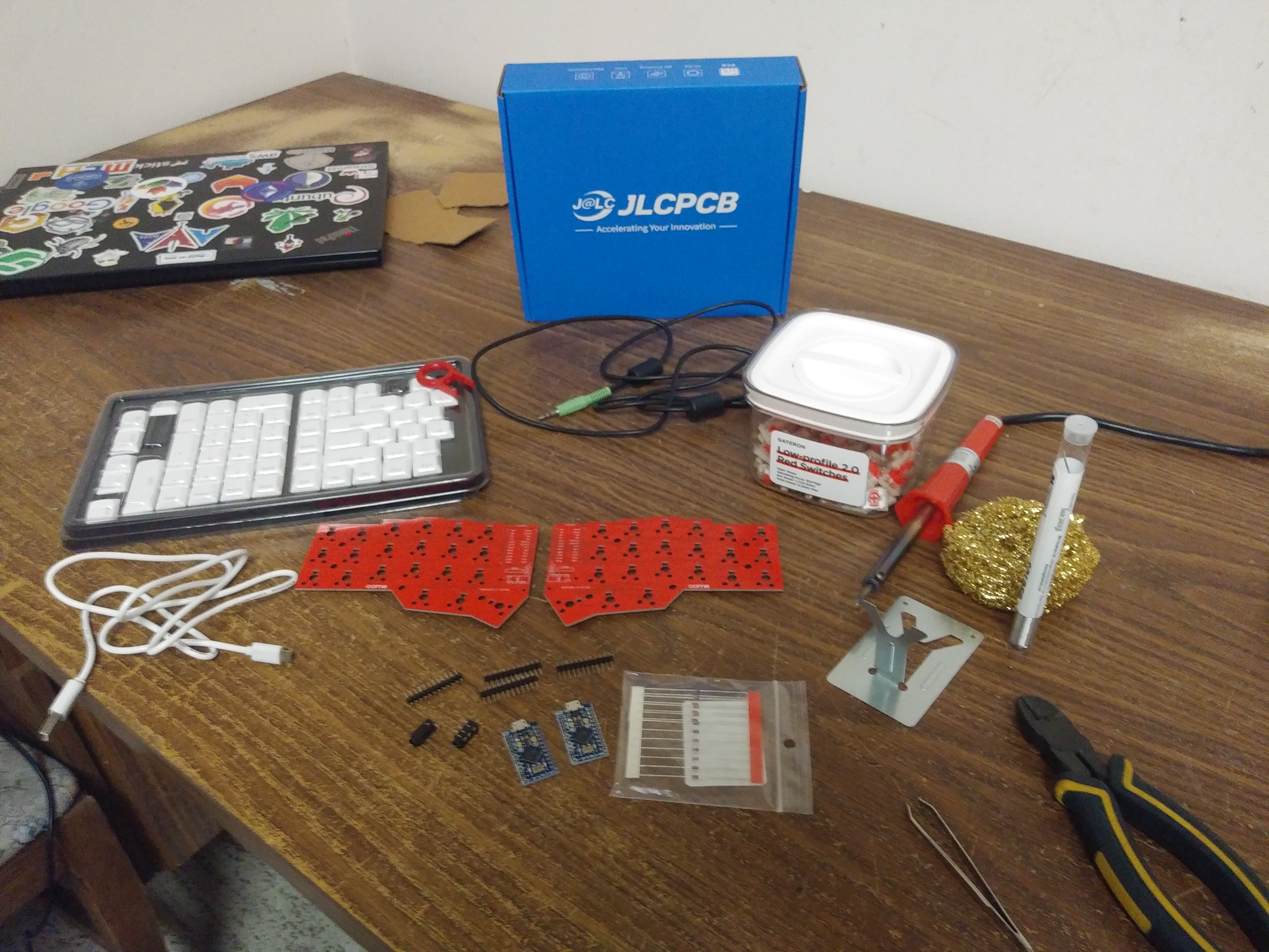 Beyond the PCB, I also have with me:
-
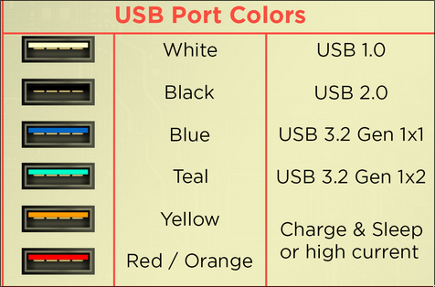
USB 2.0, Micro-USB to USB-A YOU NEED A USB 2.0 OR ABOVE FOR DATA-TRANSFER
USB 2.0 has a black inner-header. Anything that is USB 1, has a white inner-header.
-
Cheap ass soldering iron - general purpose
-
Brass sponge
-
Eyebrow tweezers (could not get proper tweezers)
-
TRRS cable
-
Keycaps from Amazon
-
Cutting pliers
-
2 x Arduino Pro Micros ATmega32U4 from Keebio
-
4 x Arduino Headers
-
2 x TRRS Jacks from Keebio
-
60% lead solder because I love lead
-
42 x 1n4148 through hole Diodes
-
Also a fan blowing to a window (not shown in the picture)
Assembling
The process to build is very tedious, lots of soldering the same components
Soldering Diodes
You first want to solder all the diodes on the PCB.
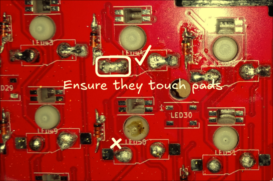
Ensure, the black part of the diode lines up with the vertical bar on the diode pad.
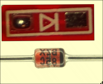
Be warned that it is very easy to remove the metal pads below the diode if you attempt to resolder the diodes. If these are gone, then there is no point of contact between the and the PCB, so ensure you get it right the first time!
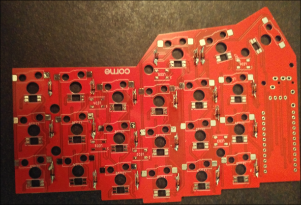
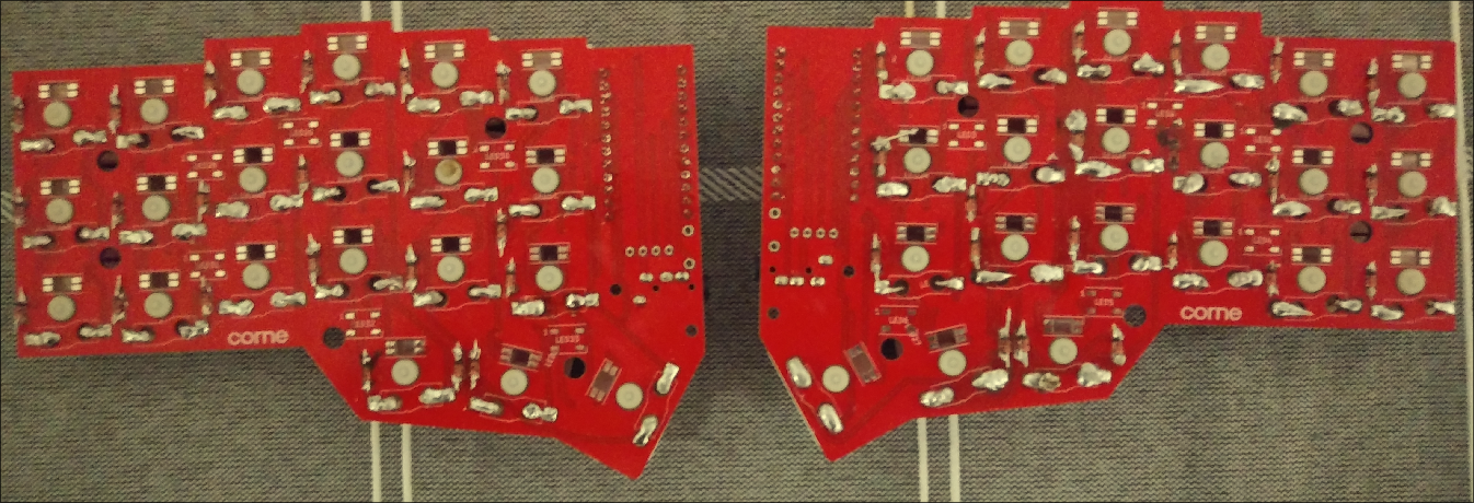
Ok, so one side of the PCB with all the diodes soldered.
Soldering Microcontrollers
I soldered my microcontrollers. This was a bad idea, but it is what I did.
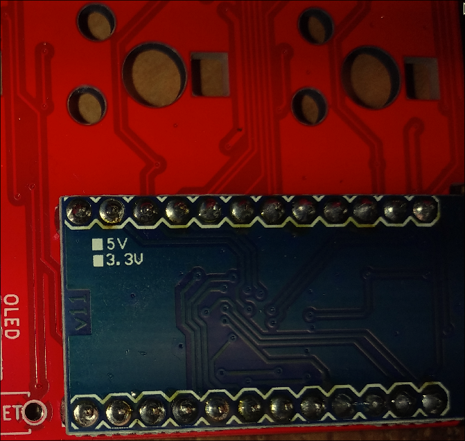 The better way is to socket them, by putting them into hot-swappable micro controller sockets. This way, you can easily remove the microcontroler when need be.
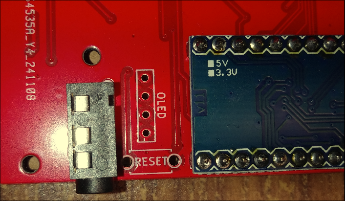
Soldering TRRS Jacks
The TRRS jacks go below the micro controller and they are very easy to solder on. There is only one orientation so you can never get it wrong.
Flashing Firmware
Pro micros support QMK keyboard firmware. This firmware allows emulation of key presses.
- Install QMK,
sudo pacman -S qmk
qmk setup
- Install my compiled keyboard layout file from: UploadThing
qmk flash davidlayout.hex
- Connect your microcontroller to your computer using your USB 2.0 cable, and then reset the microcontroller by shorting RST and GND pins
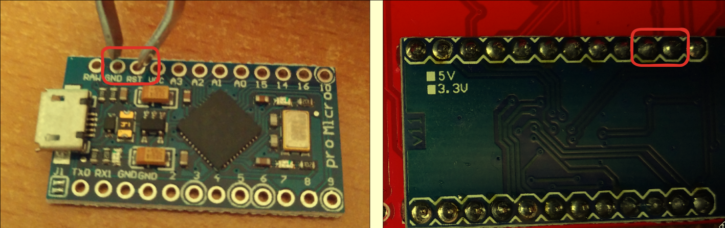
If you did it right, some LED in your microcontroller should light up, and the flashing progress should appear on your terminal.
Make sure you flash both micro controllers for both sides of the keyboard
This allows the firmware for your keyboard to be installed on your microcontroller. You can now, emulate key presses.
Emulating Key Presses
The reason why we want to emulate early on is to check if each key works on our PCB. It would suck if we assembled our entire keyboard just for a few keys to be inactive at the end. Which is what happened to me...
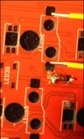
Once you have your keyboard plugged into your computer, and the LEDS on the microcontrollers light up, you can take some tweezers and short the two terminals that correspond to each key.
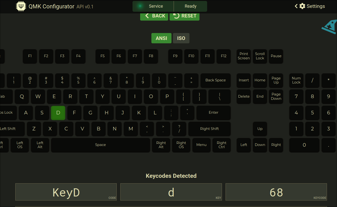
 Test, out that each key works with the QMK configurator
Soldering Switches
Ok, switches are straightforwards.
Put the switch into its socket and the solder the bottom side, ensuring that they touch the pads
This is how the board looks with all the switches soldered.
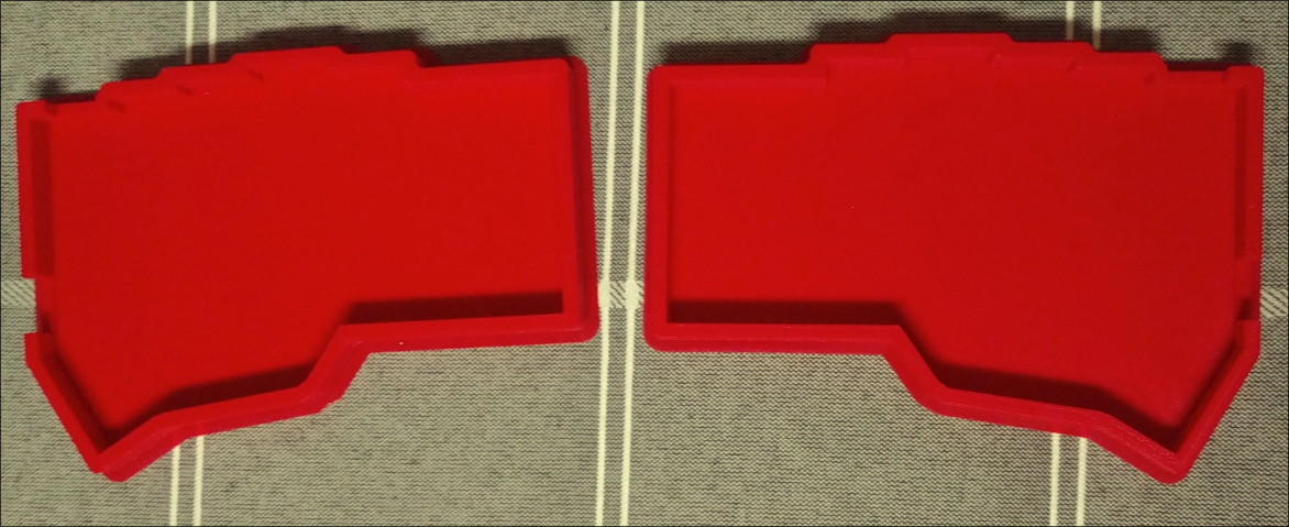
3d Printed Case
I have with me a 3d printed case. That I got from Github
Keycaps
Now place the keycaps on the board and you are done.
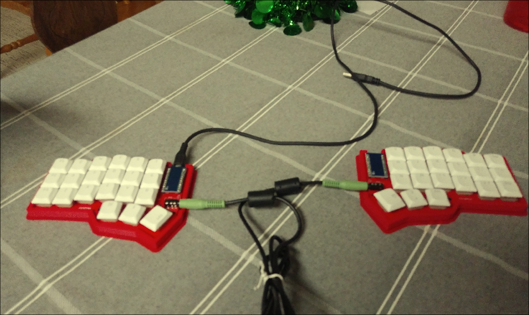
Typing Test
Now, the layout is querty, but the split makes typing so much more difficult
Other messups
Along the way I also:
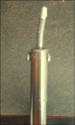
-
Dropping my soldering iron, IT IS BENT
-
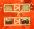
Soldered diodes backwards on a board.
One of the extra PCBs has diodes installed the completely wrong direction. Since diodes go one way, that board is useless
Anyways, I have a lot of extra parts from misorders, and I plan to continue building different ergonomic keyboards in the future.
Il be documenting the differences in the ergomonics of using these keyboards, and the effects of prolonged exposure when using these ergonomic keyboards. Really cool stuff so far though!